PCBCraft vs KiCad: an automation slice and a fabrication workflow
Compare PCBCraft’s initial workflow with the KiCad 10 guide, separating board export from a complete manufacturing project.
Last updated
Menus and supported features can change. Compare the source-check date below with your current app version.
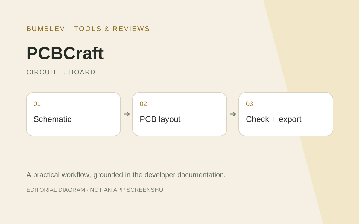
Does writing a .kicad_pcb file mean PCBCraft replaces an entire KiCad workflow? The useful distinction today is between a small agent-controlled editing path and a complete project through fabrication outputs. This is a comparison of primary documentation, not a measured performance review.
Documented scope
| Topic | PCBCraft | KiCad 10 guide |
|---|---|---|
| Organization | Schematic, board, library and check tabs | Project, schematic and board workflows |
| Automation focus | MCP and engine commands | Documented editing, checking and output tools |
| File scope | Native project and limited board export | Project, schematic, board and manufacturing outputs |
| Routing check | Basic orthogonal route limitations | Routing, design-rule checks and fabrication steps |
| Current basis | First working foundation | Versioned KiCad user documentation |
Symbols are not footprints
Schematic symbols express logical connections; footprints represent physical pads. Matching pin numbers matters during transfer. A similar-looking interface does not establish complete support for every KiCad library definition.
PCBCraft documents supported library searching and embedding while explicitly listing unsupported elements and general project import as future work. A practical adoption check starts with the actual packages needed for the task.
Compare equivalent milestones
A generated board file is an exchange milestone. It does not automatically include a schematic, project settings, design rules or production files. Open the board and inspect outline, pads, nets and tracks before moving on.
The KiCad guide separately covers schematic checking, board synchronization, routing, design-rule checks and fabrication outputs. Comparing PCBCraft’s first export with KiCad’s final manufacturing package would use different completion criteria.
A small comparison protocol
Choose the same LED sample and prepare a pin-to-pad table. Hold component packages and electrical assumptions constant. First inspect logical nets, then references and pad assignments after synchronization, then physical routing and remaining findings.
Include PCBCraft’s documented behavior after moving a footprint. Record track repairs and clearance findings rather than counting an attractive layout as completion. Use the same target and review depth in KiCad.
Save, close and reopen the native project, then inspect the exported board in KiCad. Separate initial editing time, manual correction time and recipient-side verification. Record the first failed step so the test can be repeated after an update.
Evaluating the agent
Retain component selections, net assignments, footprints and check results alongside the agent’s response. Hold provider, permissions and request constant when comparing automated runs. Software licensing and external inference costs are different considerations.
No reported findings does not establish component ratings, electrical behavior or manufacturing suitability. This series investigates editing and exchange. I would explore PCBCraft’s LED sample to understand its MCP architecture, while using KiCad’s documented full project workflow as the reference for existing designs and production requirements.
Sources and scope
Checked 19 October 2026. This introduction, tutorial and comparison use the primary sources below. They contain no claim of our own app execution or measured performance. Development builds may differ from the pinned source.
Sources & further reading
- https://github.com/tangency-labs/pcbcraft/blob/31138579e5ce1c9d9ba4ee1f83f9253581c1c689/README.md
- https://github.com/tangency-labs/pcbcraft/blob/31138579e5ce1c9d9ba4ee1f83f9253581c1c689/docs/mcp.md
- https://github.com/tangency-labs/pcbcraft/blob/31138579e5ce1c9d9ba4ee1f83f9253581c1c689/examples/led-indicator.json
- https://github.com/tangency-labs/pcbcraft/blob/31138579e5ce1c9d9ba4ee1f83f9253581c1c689/docs/kicad-libraries.md
- https://github.com/tangency-labs/pcbcraft/blob/31138579e5ce1c9d9ba4ee1f83f9253581c1c689/ROADMAP.md
- https://github.com/tangency-labs/pcbcraft/blob/31138579e5ce1c9d9ba4ee1f83f9253581c1c689/LICENSE
- https://github.com/tangency-labs/pcbcraft/blob/31138579e5ce1c9d9ba4ee1f83f9253581c1c689/NOTICE
- https://docs.kicad.org/10.0/en/getting_started_in_kicad/getting_started_in_kicad.html