FieldCraft tutorial: inspect the I-beam sample before solving
A six-step documentation guide to the official I-beam example, including units, supports, a 1,000 N load and saved conditions.
Last updated
Menus and supported features can change. Compare the source-check date below with your current app version.
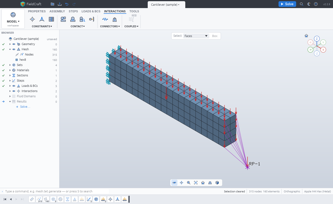
The task is to inspect the official I-beam sample and its displacement result. Starting from a predefined sample helps separate analysis settings from geometry-creation problems. These steps come from the documentation; we have not executed them for this article.
Prepare
Use an official FieldCraft build and record its version, operating system and documentation commit. Save any edits under a new filename. If the sample is absent, check the examples for that release instead of substituting a similarly named model.
| Item | Official sample |
|---|---|
| Name | ibeam |
| Geometry | 200 mm steel I-beam |
| Load | 1,000 N downward at the free end |
| Support | Documented starting face |
| Inspect | Displacement, stress, reactions and display scale |
1. Open the intended sample
Use File ▸ Samples, the start screen or the documented fieldcraft --sample ibeam route. Do not confuse it with the separate cantilever example. Read the geometry and condition list before solving.
2. Read the unit system
The examples document millimetres, tonnes, seconds, newtons and megapascals. Confirm geometry and material values use the same system. Write units next to numbers rather than assuming that every imported model uses the sample’s convention.
3. Inspect supports and force direction
Check the fixed starting face and downward free-end load against the viewport indicators. A wrong face or force direction defines a different problem. Inspect identifiers and force components where available.
4. Review the mesh and solve
The sample provides its mesh and analysis configuration. Record element type and size, then use Solve. Check completion and warnings. If solving fails, retain the first error and investigate mesh, material and constraints rather than changing several inputs at once.
5. Read numbers beside the picture
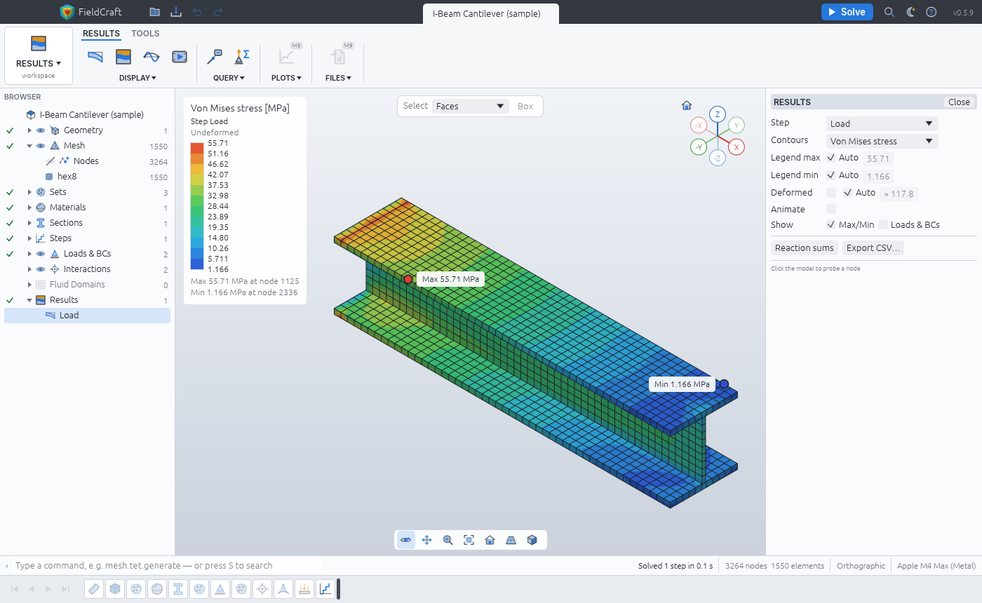
Inspect the free-end displacement and direction, stress distribution and support reaction. Read the deformation display scale. A visually exaggerated bend is not the physical displacement. Developer figures are reference material, not values measured by this article.
6. Save and reopen the analysis
Save a separate .fieldcraft project and reopen it. Confirm the geometry, material, mesh, supports and load persist. Check what results the build retains and keep the input conditions with exported images.
Expected result and limits
The detailed example describes a downward tip movement of about 0.18 mm. Compare against the same pinned example and its assumptions; do not mix it with a different README demonstration. We have not reproduced that number or established a tolerance.
If the sample is missing, align the release and documentation. For a failed solve, inspect the selected faces and warnings before changing loads. For an imported model, check unit consistency across geometry and material data.
A useful later exercise changes only the load, retaining an untouched copy of the sample. In a linear case, proportional displacement is an expected trend to investigate. Record predicted and computed values separately. Changing mesh, load and material together makes the difference difficult to interpret.
Sources and scope
Checked 19 October 2026. This introduction, tutorial and comparison use the primary sources below. They contain no claim of our own app execution or measured performance. Development builds may differ from the pinned source.
Sources & further reading
- https://github.com/tangency-labs/fieldcraft/blob/71c56068999770e83b749762b10cfed273505d1f/README.md
- https://github.com/tangency-labs/solidcraft/blob/68c72082030a999c9090c174a571b64e8244f9e8/README.md
- https://github.com/tangency-labs/fieldcraft/blob/71c56068999770e83b749762b10cfed273505d1f/docs/examples.md
- https://github.com/tangency-labs/fieldcraft/blob/71c56068999770e83b749762b10cfed273505d1f/docs/mcp.md
- https://github.com/tangency-labs/fieldcraft/blob/71c56068999770e83b749762b10cfed273505d1f/docs/oracle.md
- https://github.com/tangency-labs/fieldcraft/blob/71c56068999770e83b749762b10cfed273505d1f/LICENSE-MIT
- https://github.com/tangency-labs/fieldcraft/blob/71c56068999770e83b749762b10cfed273505d1f/NOTICE