CADCraft tutorial: draw a test rectangle and circle
A documented, six-step guide to draw a test rectangle and circle, with source screenshots, editable files and output checks.
Last updated
Menus and supported features can change. Compare the source-check date below with your current app version.
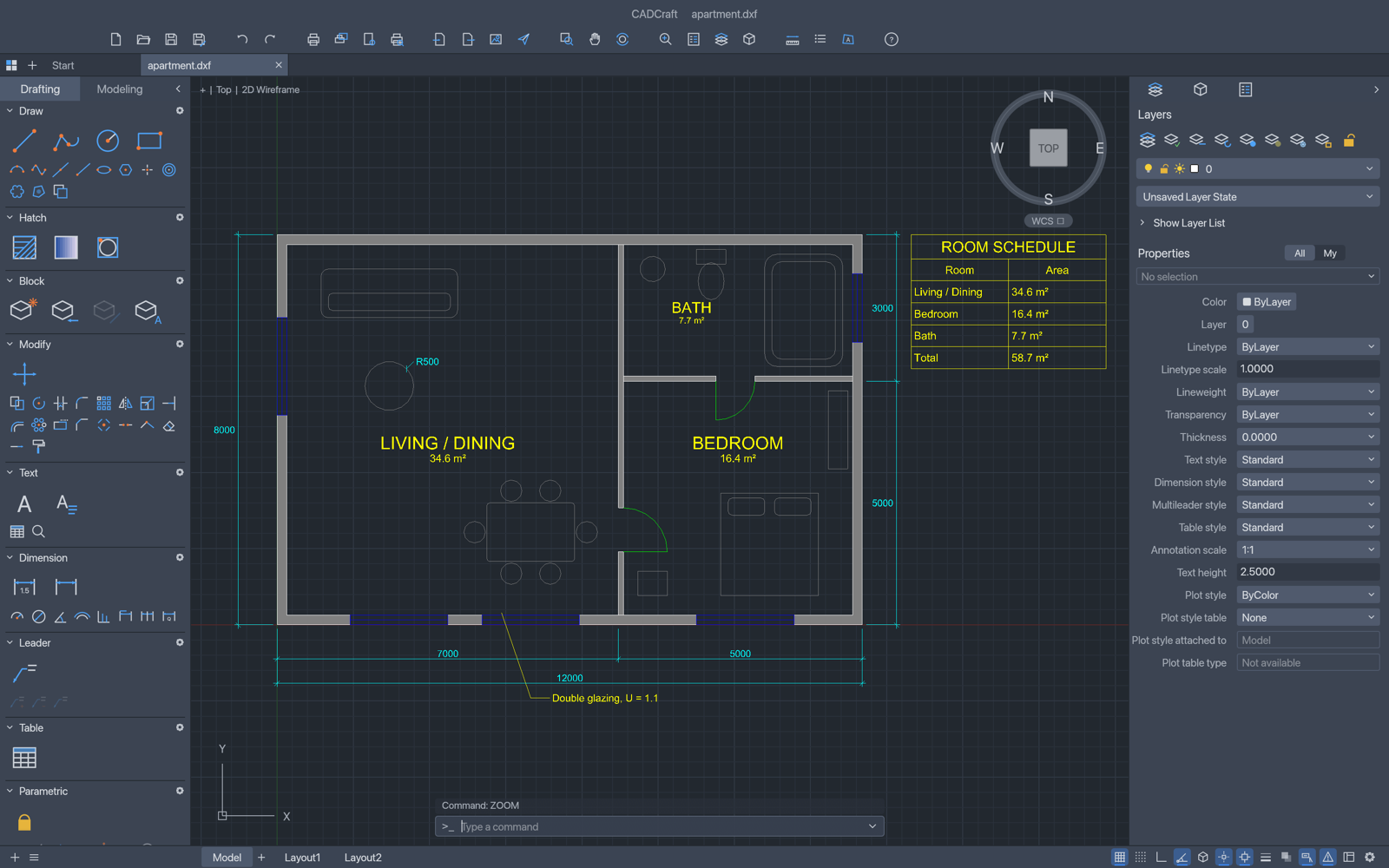
Let’s work towards one clear result: draw a test rectangle and circle. The aim is to keep something you can revise and something you can actually share, rather than learn every feature at once.
This walkthrough follows the developer’s public screens and menu descriptions. I have not run it myself, so the outputs below are expected results to verify, not a tested finished example. Keep the English menu names visible while following along; they also help when your installed version differs.
Before opening the project
Prepare: A new drawing with a rectangle from 0,0 to 10,5 and a circle centred at 5,2 with radius 1. Declare the drawing units first.
Check the official app page and release downloads for a build matching your operating system and CPU. If there is no suitable installer or the app does not start, read Get started/Quick start and known issues in the official README. Record the app version and OS when you try the task.
Use copies for the exercise and keep originals, working documents and exports in distinguishable folders. The documented stage is early development. Check the article’s source date against your installed version if a menu or supported format has changed.
Find the relevant controls
| Where to look | What it does |
|---|---|
| Command line | Enter exact commands and coordinates. |
| Layers and Properties | Inspect objects, dimensions, colour and line weight. |
| Layout and plotting | Distinguish model geometry from printed scale. |
Example settings
| Setting | Example |
|---|---|
| Rectangle | Absolute coordinates 0,0 and 10,5 |
| Circle | Centre 5,2; radius 1 |
| Working exchange | Test DXF with a new name |
| Paper check | PDF with explicit scale and page size |
Follow the task
1. Open a test drawing
Start a new drawing or use Help → Open Sample Drawing to learn the command line and view controls. Save an edited sample under a new name.
2. Enter the rectangle
Type RECTANG, then enter 0,0 and 10,5. These are absolute-coordinate examples in your declared drawing units. Do not interpret them as a physical measurement without stating those units.
3. Enter the circle
Type CIRCLE, enter centre 5,2 and radius 1. Check that the circle is inside the rectangle and inspect the actual values, not only its screen size.
4. Inspect all geometry
Use the extents route under ZOOM. Separate layers and inspect dimensions, colour and line weight. Screen zoom changes the view, not the model’s coordinate lengths.
5. Save a DXF copy
Check File → Default Save Format → DXF and use Save As…. Reopen the new file and compare retained entities and dimensions. Leave the original drawing untouched.
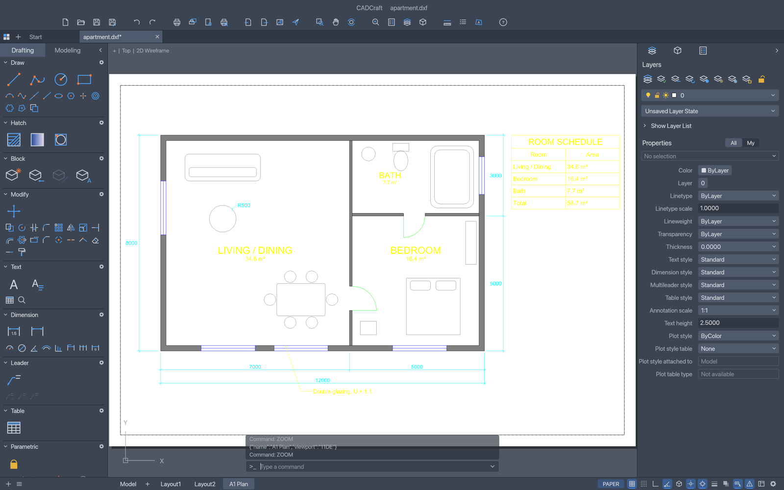
6. Plot a PDF
Use EXPORTPDF or PLOT. Inspect paper size, plot range, scale and fonts. Open the PDF elsewhere and check that lines and dimensions are readable at the intended size.
Expected output and the next small revision
Check geometry in the DXF separately from paper layout in the PDF. Verify model dimensions first, then printed scale, margins and clipped regions. Do not overwrite an important DWG with the experiment. Compare saved objects and dimensions against the source; an unsupported entity can disappear even when the rest of the drawing still looks plausible.
A new simple 2D drawing can introduce command entry and exchange. Production drawings need actual-file checks for objects that may be lost during saving. The useful completion condition is preserved geometry and a verified output scale, not merely a drawing that opens without an error.
If you get stuck
If the shape looks right but prints at the wrong size, inspect coordinate units and plot scale separately. Check displayed dimensions against the actual geometry too. Existing drawings need checks for blocks, external references and fonts. Success with this rectangle does not establish compatibility with every DWG version or entity type.
Keep the last working copy separate from the problem file. Record the exact error and the step where it appeared. Changing several settings at once makes the cause harder to find. If you replace an input file, note that it is a different test rather than declaring the original successful.
Check before scaling up
- Compare units, coordinates, curves and dimensions in the same DXF.
- Inspect blocks, external references and unsupported entities in a real DWG.
- Compare line weights, fonts and page size in PDFs at the same scale.
Agree on units before comparing identical coordinates. A length of 10 means little without them. For repeated drawings, keep geometry/dimension checks separate from PDF plotting settings. Record missing entities and manual reconstruction time; otherwise a quick export can conceal a costly repair job.
Introduction · Task tutorial · Comparison: documented differences
Sources & further reading
- https://getartcraft.com/apps/cadcraft
- https://github.com/storytold/cadcraft/blob/main/README.md
- https://www.autodesk.com/ca-en/products/autocad/features
- https://github.com/storytold/cadcraft/blob/e707ab4d7cc10102e550ad4c5bcecef1084a9baa/README.md
- https://github.com/storytold/cadcraft/blob/e707ab4d7cc10102e550ad4c5bcecef1084a9baa/crates/ui-egui/src/menus.rs